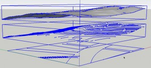
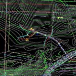
In this tutorial I will show you how to “Drape” the bottom “Street Layout” with the Topography Mesh above and show you how to successfully “Paint” the new Contour Mesh with grass and pavement.
In my Previous Post “Importing AutoCAD Civil Topography DWGs into SketchUp Pro Tutorial” you end up with Three groups of information, The top is the Topography Mesh created with the “From contours” Tool, the middle group are the “Contours” imported from CAD and the Bottom Group are the “Street Layouts” imported from the original Civil CAD DWG.
 Completed From Contours Mesh
For the Sake of this Tutorial, I have deleted the “Contour” Group. I like to use shadows to show the variations. If you are working on a more technical rendering, you may want to leave them in to show the grade change.

1. Highlight the “Street Layout” Group and go to Tools then Sandbox then Drape. Select the “Mesh” that you want to “Drape”

The “Street Layout” groups lines should now be drawn on the “Mesh” that you had created earlier.
 “Mesh” with Draped “Street” Lines
TIPS:
If you have performed the steps from the previous post “Importing AutoCAD Civil Topography DWGs into SketchUp Pro Tutorial”, then this process should go smoothly since the Model had been “Simplified” If you have not followed those steps and are having issues, please look through the previous post.
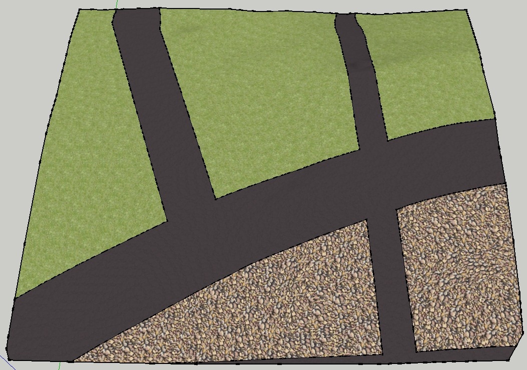
2. At this point you may notice that the “Streets” lines have not connected completely with the edge of the Topography Mesh. Now this sample image has been exagerated to show the steps to rectify this situation. The best way to analyze this is to “Paint” the surface and see where the planes do not connect.
 “Mesh” with open Texture Planes
In the image above you can see that the Grass painted areas include the “Streets” and “Walks” that we meshed earlier, I painted the closed surfaces in a stone texture for diagrammatic purposes. The Grass surfaces are including the “Street” surfaces.

3. To fix these open surfaces first go to View then Hidden Geometry
 Site with “Hidden Geometry” Visible
You will notice that the “Mesh” is created by connected Polygonal planes that create the effect of a 3D topography.
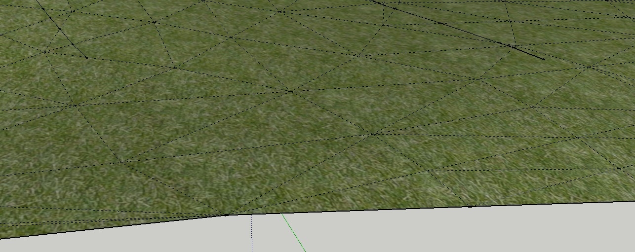
To fix the unconnected lines and to close the “Street” Surfaces simply use the Line tool and draw on the individual polygonal planes to “split” the surfaces and close the plane.
Right Click on the “Mesh” and select Edit Group, Select the Line tool from the palette and connect the “Hidden Geometry” lines
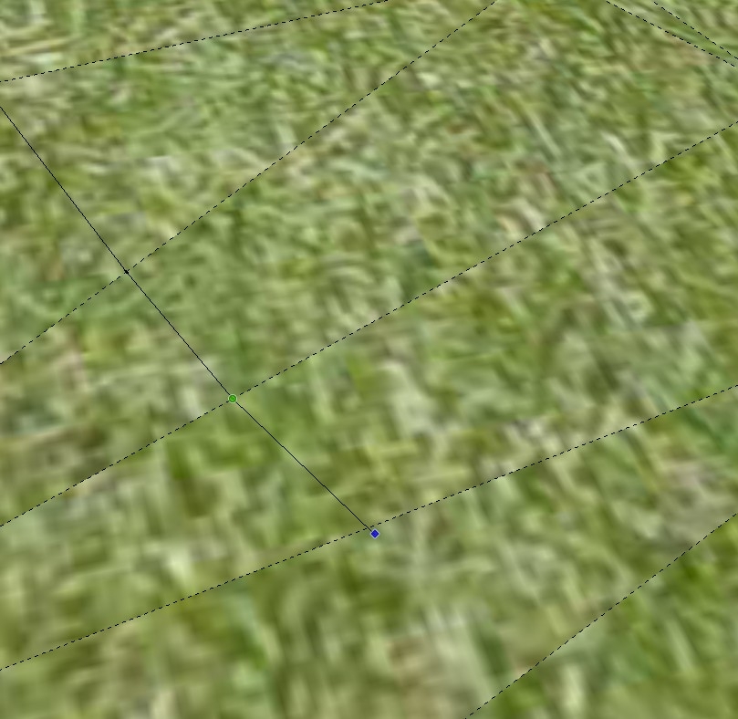
TIPS:
– If you have large gaps like the ones I am showing here (usually you wouldn’t and they would be small areas to connect) you may have to guess at the proper connection point on the other side of the hidden plane, Using “Construction” lines may help to keep you in the right direction
– Sometimes you will not be able to find the gap that is keeping your surface from being closed. You can “paint” the individual hidden planes with the paint bucket, sometime this is the only way to get the surfaces that you are looking for.
 Completed painted draped “Mesh”

